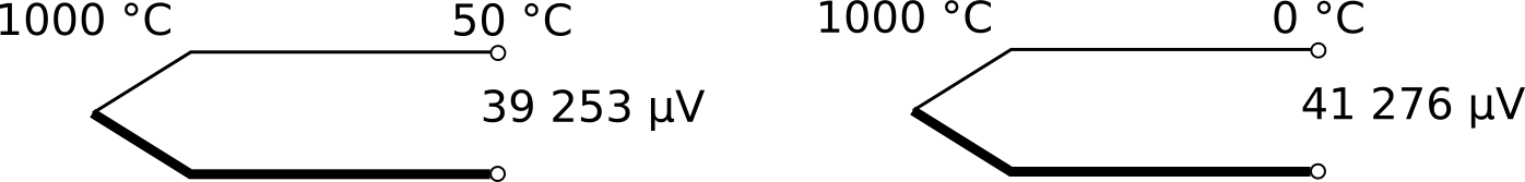
The amount of voltage that is generated by a thermocouple depends on the difference between the temperatures of its measuring (or “hot”) junction and reference (or “cold”) junction.
Q: Where exactly is the cold junction?
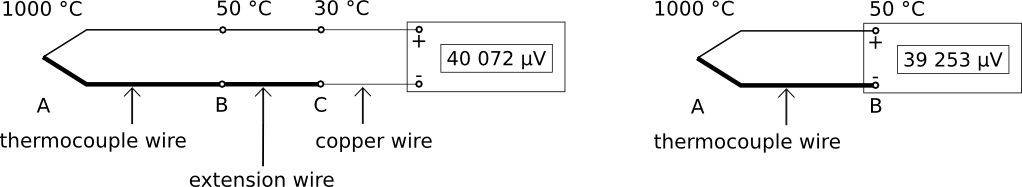
A: It is where the thermocouple wires end, and copper wires continue the circuit to the readout (display unit), that is, at positions C and B, respectively, in the two diagrams below.
Q: What is electronic Cold Junction Compensation (CJC)?
A: It is when the readout measures the temperature of the cold junction and compensates for its difference from 0 °C, by adding or subtracting some voltage to the thermocouple signal. (Since 0 °C is the cold junction temperature used in the thermocouple reference tables, thermocouple voltages for a cold junction temperature of 0 °C must be used when converting voltage to temperature using the reference tables.)

When the cold junction temperature is measured inside the readout terminals, it is often called “internal” CJC.
The other option is external or manual CJC, where the cold junction is outside the readout and is not measured or determined by the internal temperature sensor, but usually input by the user:

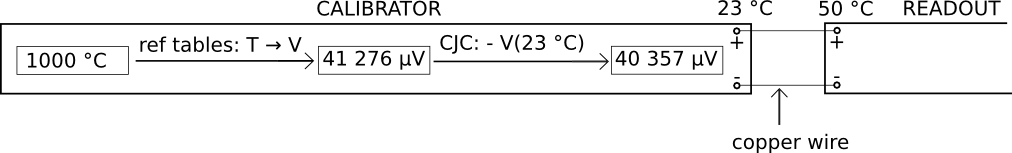
Q: How is internal CJC implemented during electrical simulation of a thermocouple?
A: The calibrator (voltage source) measures the temperature of its terminals, and compensates its output accordingly:
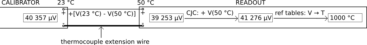
The readout measures the temperature of its terminals, and compensates its input accordingly:
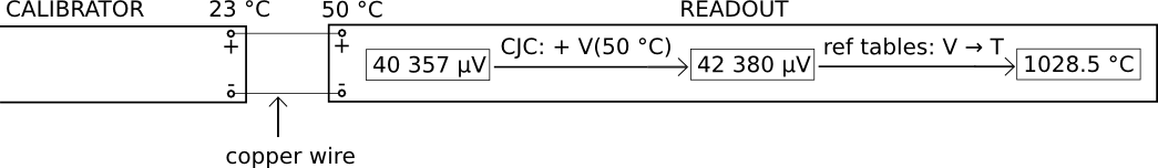
So, in the example above, there is an error of approximately 28.5 °C, caused by the difference between the temperatures of the terminals of the calibrator and readout.
Q: How can this error be avoided?
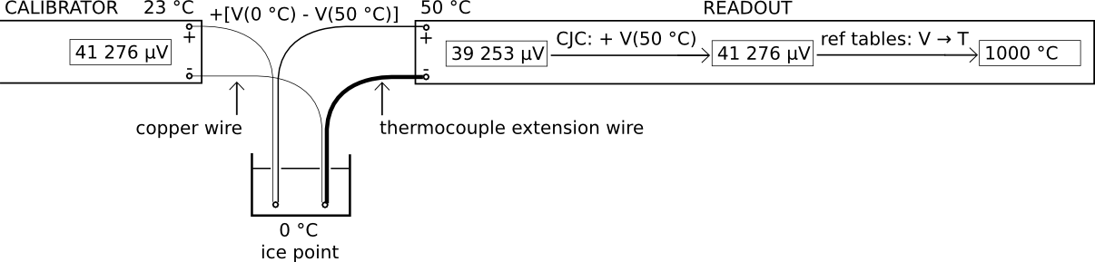
A: By making the connection using thermocouple extension wire:
If the calibrator does not have electronic CJC (or its CJC is switched off), an ice point must be used:
Exercises:
1. Use the type K thermocouple reference tables to reproduce the voltage values indicated in the above sketches. (Your calculated values should agree with those above to within 1 µV.)
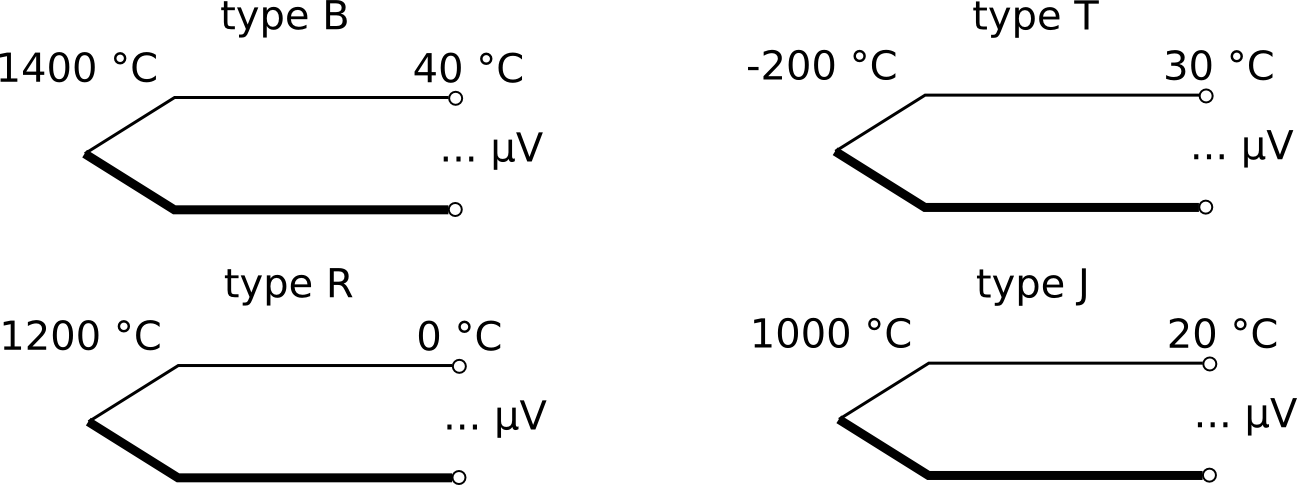
2. What is the voltage output of each thermocouple below, to the nearest 1 µV, if it follows the relevant reference tables exactly?
3. Explain how to connect a thermocouple readout without CJC to a calibrator with CJC, in order to calibrate the readout by electrical simulation. (Note: This is a situation unlikely to be encountered in real life.)
(Contact the author at lmc-solutions.co.za.)
dear Hans
I have take a look on you writtings, are very interesting material for me as a metrologist beginer in the field of thermometry.
Thanks, it will be helpefully
Sergio Machava
Félicitation pour vos information, ils sont logique et compréhensible et enfin il permet finalement de comprendre vraiment le thermocouple .Beaucoup de site sur internet sont nuisible à une bonne compréhension des thermocouples .Vos informations sont complémentaires avec Texas instrument http://www.ti.com/lit/ml/slyp161/slyp161.pdf. Merci encore.